Featured News - Current News - Archived News - News Categories
Meeting the challenges of thin-gauge sheet extrusion
Meeting the challenges of thin-gauge sheet extrusion
SUSHANT JAIN - Senior Scientist
Sheet extrusion is characterised by the production of double-polished sheet which is cooled between rollers which exert high closing forces. Thinner film is produced by the casting process where the film is thin enough to be cooled only on one side by a polished roller. Thingauge double-polished sheet at about 200 microns thick is at the borderline between cast film and typical double polished sheet. This thickness threshold depends on the material being extruded and its thermal and physical properties. The production of thin-gauge sheet presents unique challenges which will be examined here.
Raw material considerations
It is extremely important to deliver melt at a uniform temperature and flow rate in the transverse and machine directions while producing thin-gauge sheet. This requires that variability in the raw material input must be minimised. In the majority of cases, the sheet
produced is used for thermoforming in a downstream operation. Depending on the shape of the thermoformed part, the process can generate up to 70% regrind. In order to make the process economical, all of this regrind is re-used in the extrusion process. The amount of regrind used and its bulk density affects uniformity of the material input. These variations in raw material can cause head pressure variations which should be minimised (± 3 bar). The
extruder feed screw should be designed to process raw material bulk density variations that can be as high as 50% to 100%. In addition, a gear pump, static mixer, and back pressure valve upstream of the gear pump are installed on the line to improve homogeneity of melt
that is delivered to the die.
Process repeatability and stability are important
The process operating window for thin-gauge sheet production is tighter than that used for heavy gauge sheet. For example, nonuniformity in melt temperature that is delivered to the sheet die can cause premature freezing of melt entering the primary nip point. Any frozen melt entering the nip results in locally uneven surface quality of the sheet due to poor polish. It is important that

Table 1:
Recommended melt temperatures.
the melt temperature be uniform within a tight band across the sheet width and over time
from day to day to maintain sheet quality. It is required that the temperatures in the extruder
and downstream components including the melt pipes, screen changer, gear pump, and die be maintained within precisely controlled limits. The chrome roller temperature settings also have to be set high enough to prevent quick freezing on the middle roller. Table 1 lists typical melt temperatures for various materials. Precise control and coordination of roller speeds is very important to produce high-quality thin gauge sheet using different materials. The roller speeds should be maintained within ± 0.05-0.10% of base speed. Poor roller speed control will introduce undesirable orientation and transverse direction lines in the form of chatter marks due to uncontrolled stretching of the sheet. Proper tension is maintained in the sheet web by controlling the relative speeds of the main chrome rollers and pull rollers. This tension should be in the range of 3.5-7 N/cm (2-4 PLI - lb/linear in.) across the width of the sheet.
Monitor die lip to roll nip distance
It is desirable to minimise the distance between the die lip exit and the primary roller nip, which is typically 100-200 mm (3.93"-7.87") depending on line size. This becomes even more important in the case of extruding thin-gauge sheet. Polymer melt leaving the die is exposed to air and tends to freeze off prematurely which prevents uniform polish in the roller stack. Also, a longer distance to the roller nip can result in excessive necking down of the sheet width. This can introduce undesirable orientation in the sheet and can create a bead at the edge of the sheet which prevents polishing at the sheet edges and results in higher edge thickness.
Contouring of the nose of the sheet die and using a smaller lead roller diameter helps to bring the sheet die lips closer to the roller nip. If external deckles are used they protrude from the die lip and prevent the close approach of the die. It is recommended that internal pinch shim deckles be used to control the sheet width, thereby allowing close approach of the die lip to the roller nip.
Roller construction and quality play an important role
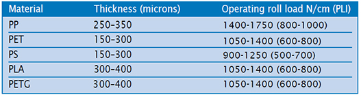
Polishing of thin-gauge sheet requires high roller closing forces. Table 2 lists the recommended roller loads to make high-quality thingauge sheet. Running at these high roller operating loads requires appropriately designed and constructed rollers. The tolerances of the roller journal and bearings have to meet tighter requirements. C1 spherical tapered roller bearings are used which provide a total indicated run out of 13 microns. The overall roller stand assembly needs to operate while maintaining a precise nip gap under heavy loads that are applied to polish the thin-gauge sheet. This also necessitates highly polished roller surfaces, typically at 0.5 Ra or better.
 How to counteract roll deflection
Due to design limitations, the roller closing force is exerted on the ends of the rollers where they are supported. As the sheet passes through the roller nip it exerts a force across the entire width of the roller face. This can cause the roller to deflect under operating conditions. The defection results in a thick band around the centre of the sheet. Since the overall sheet gauge is only 250 microns, even a 50 micron roller deflection will show up as 20% variation in sheet thickness. The target variation is typically ± 3%.
Three methods are employed to counteract roller deflection described above (see figure 1). The first is crowning the roller to a larger diameter in the centre which has the effect of compensating or roller deflection in the centre. This method works for a specific process and material. However, when the extent of roller deflection changes this method does not provide an effective solution. The second method is counter bending rollers which are built with a stiffer construction in the centre of the roller. This design also works at the designed conditions, but has a narrow operating window. Roller closing forces for this design are limited to 1400 N/cm (800 PLI) due to spring constant and design considerations.
The third method is to skew the axis of the lead roller by a controlled amount. This preferentially increases roller separation
at the edges while keeping it unchanged at the centre. Using this technique, the amount of roller skew is matched to the extent of roller deflection at the centre. This provides uniform sheet thickness for a wide range of material thicknesses and operating conditions.
Minimising sheet sag and droop
As the melt curtain leaves the sheet die lips, it is critical to introduce it directly into the primary nip without contacting either the lead or bottom roller. Any such contact causes premature skinning of the melt. Subsequently, the sheet receives an uneven polish and exhibits surface imperfections. The vertical roller stack is used very often due to its applicability to various materials and gauges. As shown in figure 2, the rollers are positioned vertically and the melt curtain enters the nip in a horizontal orientation. Gravity causes the melt to sag and contact the middle roller before entering the nip, resulting in partial freeze o of the melt before being polished in the nip. For thin-gauge sheet production, gravity effects of a vertical roller stand configuration are of particular concern. One way to address this is to position the nip slightly lower than the die lip as shown in figure 2.
The J-stack is an alternative configuration of the roller stand. In this case, the melt curtain enters the die lips at a 45 degree angle to the vertical. It partially reduces the gravity effects and provides additional wrap around the centre roller for increased cooling.
The most effective roller configuration for thin-sheet production is the horizontal roller stand as shown in figure 4. Here, the melt curtain enters the primary roller nip vertically as shown in figure 3. Consequently, unfavourable effects of sheet sag and droop are eliminated. Also, it provides for a wider process window to position the rolling melt bank at the nip entrance against the centre roller.
 When using a vertical roller stand, an air bar can be installed on the underside of the die to blow air upward against the melt curtain. This is a means to help position the melt bank against the middle roller and minimise the effects of rapid freeze off of the sheet before entering the primary nip.
Table 2:
Recommended roller loads to make high-quality thingauge sheet.
Processing Technologies International, LLC, 2655 White Oak Circle, Aurora IL 60502 © 2022 Processing Technologies International, LLC P: 630.585.5800 F: 630.585.5855